Wiring a ceiling fan and light with diagrams ptr 3 sd switch diagram inspirational hunter of motor fans how to install your cpo s 20 wire พ ดลม installation instructions for remote receiver single c17 pre 1950 antique collectors association afca forums internal data

Wiring A Ceiling Fan And Light With Diagrams Ptr

3 Sd Ceiling Fan Switch Wiring Diagram Inspirational Hunter Of Motor Light

Hunter Fans How To Install Your Ceiling Fan Cpo S

20 Ceiling Fan Wire Diagram พ ดลม

3 Sd Ceiling Fan Switch Wiring Diagram Inspirational Hunter Of Motor Light

Installation Instructions For Hunter Ceiling Fan

Hunter 3 Sd Fan Switch Wiring Diagram Ceiling

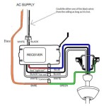
How To Wire A Ceiling Fan With Remote Receiver

Ceiling Fan Wiring Diagram Single Switch

Wiring For A Hunter C17 Ceiling Fan Pre 1950 Antique Collectors Association Afca Forums

Hunter Fans Internal Wiring And Data

Wiring Diagram For A Harbor Breeze Ceiling Fan 4 Wire Switch W Hunter Fans

Ceiling Fand Wiring Diagram Fan Motor

Hunter Ceiling Fan 4 Wire Switch Repair

Harbor Breeze Wiring Diagram Ceiling Fan Switch Installation

Ceiling Fan Remote Conversion Final Connections Wiring With

Ceiling Fan Wiring Diagram Switch Loop

Removing Old Ceiling Fan Wiring A New

How To Install A Ceiling Fan Hunter

3 Way Wiring Ceiling Fan With Remote For Two Wire Diy Home Improvement Forum
Wiring a ceiling fan and light with 3 sd switch install your 20 wire diagram hunter remote receiver single for c17 fans internal data
Related Posts