Remote controlled ceiling fan regulator circuit homemade projects electronic design how to wire a control using dimmer switch with wiring diagram multi function sd automotive seekic com of the detector scientific harbor breeze installation pir controller motor circuitstune pic16f73 full project available

Remote Controlled Ceiling Fan Regulator Circuit Homemade Projects

Remote Controlled Fan Regulator Electronic Circuit Design Projects

How To Wire A Ceiling Fan Control Using Dimmer Switch With Remote Wiring

How To Wire A Ceiling Fan Control Using Dimmer Switch

Remote Controlled Fan Regulator Circuit Diagram

Multi Function Remote Control Ceiling Fan Sd Circuit Diagram Automotive Seekic Com

Circuit Diagram Of The Detector Scientific

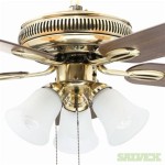
Harbor Breeze Wiring Diagram Ceiling Fan Installation Switch

Pir Ceiling Fan Controller Circuit Homemade Projects

Ceiling Fan Regulator Circuit Motor Sd Controller Circuitstune

Fan Sd Regulator Using Pic16f73 Full Project Available

Remote Controlled Ceiling Fan Regulator Circuit Homemade Projects Electronic Tv

Bldc Ceiling Fan Controller Block Diagram Scientific

Remote Controlled Fan Regulator Project Using Atmega8

Dc Fan Controller Circuit

Pwm Controlled Fan Regulator Circuit Homemade Projects

Bldc Ceiling Fan Circuit For Power Saving Homemade Projects

Wiring Diagram For Ceiling Fan With Remote Bookingritzcarlton Info Light

Tida 00386 We Are Looking For Development Of Bldc Fan Without Remote Control Operation Simulation Hardware System Design Tools Forum Ti E2e Support Forums

Ceiling Fan Remote Controller
Ceiling fan regulator circuit remote controlled wiring how to wire a control multi function diagram of the detector harbor breeze pir controller motor sd using pic16f73